This website uses cookies so that we can provide you with the best user experience possible. Cookie information is stored in your browser and performs functions such as recognising you when you return to our website and helping our team to understand which sections of the website you find most interesting and useful.
Static VAr Compensator (SVC)
A Static VAr Compensator (or SVC) is an electrical device for providing fast-acting reactive power on high-voltage electricity transmission networks. SVCs are part of the Flexible AC transmission system device family (FACTS), regulating voltage and stabilizing the system.
We provide a complete turnkey delivery of the project including civil works. Furthermore, we can also provide consultancy support for the assessment of the SVC specification.
Wind Farms
Due to increase of wind energy, the Transmission System Operators (TSO) put grid code requirements on the wind parks to ensure grid stability such as reactive power control and ride-through capability. A centrally placed SVC at the Point of Common Coupling (PCC) can be used to solve these issues in wind farms and have the following benefits:
- Voltage Stabilization
- Fault Ride Through (FRT)
- Reactive Power Balance
- Flicker Reduction
Inverter / Ondulator
OPERATING PRINCIPLES, DESIGN AND GENERAL FEATURES OF THE DEVICE
An inverter transforms direct current (DC) into alternating current (AC), in this case, at a constant frequency.
Input source (DC)
The DC input can come from solar panels, rectifiers – chargers, batteries, DC bars, etc. The voltage is usually variable because the power sources operate in highly volatile situations. For that reason, the Jemainverter is designed to accept a wide margin of variation in input voltage while maintaining the desired output parameters.
Transfer by-pass
The inverters work on-line and usually include a static transfer by-pass to an auxiliary support grid for emergencies and a manual by-pass for maintenance work.
Device design
The device has excellent dynamic behaviour with IGBT transistors. It’s controlled by a microprocessor that governs the unit in response to different keywords and signals it receives and informs the user of its status. If it includes a by-pass, it synchronises with the auxiliary grid. Control functions:
- History: last 250 alarms with time and date
- Automatic control: programmable start up and shut down
- Diagnostics: visualise and transmit the status of the device
- Measurements:
- Vef and Ief of all phases
- Active, apparent and reactive power
- Internal system temperatures
- yield, power and frequency factor
- Test: automatic, local/remote, periodic and programmable
- Digital settings: parameters adjustable by keyboard
- Configurable: basic system functions can be defined
- Tips for using the keyboard
General features of the device
- Digitally synthesised perfect sine wave output
- High frequency stability and output voltage
- High performance, simplicity and reliability
- Excellent behaviour with non-linear unbalanced loads
- Multiprocessor digital control, PWM modulation
- Interface using a display, keyboard, LEDs and serial communication
- Built in galvanic isolation transformer
- Can optionally operate in parallel with other units
Features
- Input: 24 / 48 / 110 / 125 / 220 Vdc – Voltage margin depending on design
- Output: From 1 to 1300 kVA – Single-phase 220 VAC ± 1 % – Three-phase 220 / 380 / 400 VAC ± 1 % – Voltage adjustment ± 5 % Vn – Frequency 50 / 60 / 400 Hz ± 0.1% – allowable cos 0.6 capacitive / 0.4 inductive – Harmonic greater 3 % – Max. distor. THD global linear load < 3 % – non-linear load < 5 % – Dynamic response ± 5 % – Response time 30 ms – Crest factor 3 – Yield 80 – 93 %, depending on power
- Options Transfer by-pass, without cut-off– LBP line stabiliser transformer – Redundant – Operation in parallel with other units –Anti-earthquake Class 1E – Output distribution board – Manoeuvre board – Adaptation to diverse regulations (MIL, UL …)
- Design: Self-supporting metal cabinet – IP20 to IP54 Protection – Colour RAL 7032 (standard)
All the features above can be modified on demand.
Static frequency converter
OPERATING PRINCIPLES, DESIGN AND GENERAL FEATURES OF THE DEVICE
Operating principle
Static frequency converters are used to feed loads that require AC power at a fixed frequency different from what is available from the grid. Using an intermediate DC transformation, the device can deliver that power under the required conditions.
Subsequently, one unit consists of 2 sub-subsystems:
- Rectifier: converts incoming AC voltage to DC
- Inverter: converts DC voltage to AC at the output at the required frequency
Batteries can optionally be added to the system so it can be autonomous in the event of a grid failure.
Device design
The device has excellent dynamic behaviour with IGBT transistors. It’s controlled by a microprocessor that governs the unit in response to different keywords and signals it receives and informs the user of its status.
Control functions:
- History: last 250 alarms with time and date
- Automatic control: programmable start up and shut down
- Diagnostics: visualise and transmit the status of the device
- Measurements:
- Vef and Ief of all phases
- Active, apparent and reactive power
- Internal system temperatures
- Output
- Cos and input and output frequency
- Test: automatic, local/remote, periodic and programmable
- Digital settings: parameters adjustable by keyboard
- Configurable: basic system functions can be defined
- Tips: using the keyboard
General features of the device
- High power factor at input: 20.95
- Digitally synthesised perfect sine wave output
- High frequency stability and output voltage
- High performance, simplicity and reliability
- Excellent behaviour with non-linear unbalanced loads
- Multiprocessor digital control, PWM modulation
- Interface using a display, keyboard, LEDs and serial communication
- Built in galvanic isolation transformer
- Can optionally operate in parallel with other units
- Can include an auxiliary power supply form 28 Vdc up to 1000 A
Features
- Input: Three-phase 220 / 380 / 400 VAC + 15 % – 10% – Frequency 50 / 60 Hz ± 5% – power factor up to 0.9
- Output: From 5 to 1300 kVA – Frequency 50 / 60 / 400 Hz ± 0.1 % – Single-phase 220 VAC ± 1 % – Three-phase 220 / 380 / 400 VAC ± 1 % – Voltage adjustment ± 5 % Vn – allowable cos 0.6 capacitive / 0.4 inductive – Harmonic greater 3 % – Max distor.THD global linear load < 3 % – non-linear load < 5 % – Dynamic response ± 5 % – Response time 30 ms – Crest factor 3 – Yield 80 – 93 %, depending on power
- Options: Pb or NiCd batteries – 6 or 12 pulses – Anti-harmonics filter – LBP line stabiliser transformer – 28 VDC / 160 a 1000 A Auxiliary source – Redundant – Operation in parallel with other units – Class 1E Anti-earthquake – Output distribution board – Manoeuvre board– Adaptation to diverse regulations (MIL, UL, …)
- Design: Self-supporting metal cabinet – IP20 to IP54 Protection – Colour RAL 7032 (standard)
All the features above can be modified on demand.
Uninterrupted Power Supply System (UPS)
OPERATING PRINCIPLES, DESIGN AND GENERAL FEATURES OF THE DEVICE
Operating principle
A UPS ensures AC electrical supply to the loads it serves by using batteries. In addition, it filters disruptions, harmonics, voltage spikes etc. that may appear in the grid. Those features are demanded by critical or vital loads that require high quality trustworthy power.
A UPS is made up of 4 sub-systems:
- Rectifier: converts incoming AC voltage to DC
- Batteries: stores the required energy
- Inverter: converts DC voltage to AC at the output
- By-pass: continuously selects the best grid (aux. or)
Device design
The device has excellent dynamic behaviour with IGBT transistors. It’s controlled by a microprocessor that governs the device in response to different keywords and signals it receives and informs the user of its status.
Control functions:
- History: last 250 alarms with time and date
- Automatic control: programmable start up and shut down
- Diagnostics: visualise and transmit the status of the device
- Measurements:
- Vef and Ief of all phases
- Active, apparent and reactive power
- Internal system temperatures
- Output
- Cos q> and input and output frequency
- Test: automatic, local/remote, periodic and programmable
- Digital settings: parameters adjustable by keyboard
- Configurable: basic system functions can be defined
- Tips for using the keyboard
General features
- High power factor at input: 20.95
- Digitally synthesised perfect sine wave output
- High frequency stability and output voltage
- High performance, simplicity and reliability
- Excellent behaviour with non-linear unbalanced loads
- Multiprocessor digital control, PWM modulation
- Interface using a display, keyboard, LEDs and serial communication
- Built in galvanic isolation transformer
Can optionally operate in parallel with other units
Features
- Input: Three-phase 220 / 380 / 400 VAC + 15 % – 10% – Frequency 50 / 60 Hz ± 5% – power factor up to 0.9
- Output: From 5 to 1300 kVA – Frequency 50 / 60 / 400 Hz ± 0.1 % – Single-phase 220 VAC ± 1 % – Three-phase 220 / 380 / 400 VAC ± 1 % – Voltage adjustment ± 5% Vn – allowable cos 0.6 capacitive / 0.4 inductive – Harmonic greater 3 % – Max distor.THD global linear load < 3 % – non-linear load < 5 % – Dynamic response ± 5 % – Response time 30 ms – Crest factor 3 – Yield 80 – 93 %, depending on power
- Options: Pb or NiCd batteries – 6 or 12 pulses – Anti-harmonics filter – LBP line stabiliser transformer – 28 VDC / 160 a 1000 A Auxiliary source – Redundant – Operation in parallel with other units – Class 1E Anti-earthquake – Output distribution board – Manoeuvre board– Adaptation to diverse regulations (MIL, UL, …)
- Design: Self-supporting metal cabinet – IP20 to IP54 Protection – Colour RAL 7032 (standard)
Rectifiers / Battery chargers
OPERATING PRINCIPLES, CHARGE LIMITS AND LEVELS AND GENERAL DEVICE FEATURES
Operating principles
A rectifier transforms alternating current (AC) into direct current (DC). Its normal function is charging batteries and keeping them in optimum conditions while, at the same time, providing DC power for other loads. Consequently, it’s essential that the unit takes into account what kind of batteries it’s feeding (Pb or NiCd) when operating.
It works automatically and continuously evaluates the status and temperature of the batteries and other system parameters in order to guarantee stable voltage and low ripple.
It can incorporate load disconnection manoeuvres for the end of autonomy, thermal-magnetic distribution, fault localisation, grid analysers, etc.
Battery charge limits and levels
With sealed Pb batteries, only two current levels are used (float and charge), while three are used for open Pb and NiCd batteries: float, fast charge and deep charge.
- Float: for maintaining the battery when already charged depending on the temperature.
- Fast charge: Done in the shortest time possible to restore capacity lost by the battery during discharge; at limited current and final voltage of stabilised charge.
- Deep charge or deformation: Periodic manual operation to equalise the battery elements; at limited current and final voltage of stabilised charge. Done in a vacuum.
Shift from float to fast charge and vice-versa:
- Automatically: when current above a specified value is suddenly absorbed, adjustable. And the opposite, after the absorbed current drops.
- Manually (optional): pushing a local / remote button.
General features of the device
- Complete, automatic wave rectifier
- High power factor at input, up to 0.9
- High output voltage stability, rippled up to 0.1% RMS
- High performance, simplicity and reliability
- Can be used in parallel with other units
CARACTERÍSTICAS
Entrada: Monofásica 220 VAC, + 15%, – 20% – Trifásica 220 / 380 / 400 VAC, + 15%, – 20% – Frecuencia 50 / 60 Hz, ± 5% – Factor de potencia hasta 0,9
Salida: 24 / 48 / 110 / 125 / 220 VDC, ± 0,5% – De 10 a 10.000 A – Rizado hasta 0,1% r.m.s. – Rendimiento hasta 94%, según potencia
Opciones: Baterías de Pb ó NiCd – 6 ó 12 pulsos – Filtro anti armónicos – Redundante – Operación en paralelo con otras unidades – Antisísmico Clase 1E – Cuadros de distribución de salida – Cuadros de maniobra – Detector de faltas a tierra – Localizador de faltas a tierra – Analizador de redes – Adaptación a normativas diversas (MIL, UL, …)
Diseño: Armario metálico autoportante – Protección IP20 a IP54 – Color RAL 7032 (típico)
Todas las características anteriores pueden adaptarse bajo demanda.
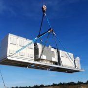
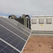
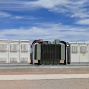
STATCOM
STATCOM for grid integration in renewable energy plants
Jema provides a complete range of STATCOMs from 1 Mvar to 40 Mvar (increasable using parallel devices), for integration in renewable plant grids.
Significant features
- Two product ranges: LV for power between 1 and 6 Mvar and a multi-level MV system from 10 to 40 Mvar.
- Compact systems up to 40 Mvar in a 40-foot container.
- MMC Systems with integrated redundancy (hot spare).
- Air / water cooling.
- Operating temperature increase up to 50º C.
- Remote monitoring.
Jema Project in Teesside, United Kingdom
/by defactoNewsletter subscription
Latest news
 What is electromobility project management like in France?25 March, 2024 - 12:10 pm
 Megawatt Charging System – MCS applications24 March, 2024 - 3:24 pm
 Interview with Miriam Azurmendi, responsable for heavy-duty charging systems21 March, 2024 - 3:03 pm
 Features of Jema Energy inverters14 February, 2024 - 10:50 am
CATEGORÍAS
Strictly Necessary Cookie should be enabled at all times so that we can save your preferences for cookie settings.
If you disable this cookie, we will not be able to save your preferences. This means that every time you visit this website you will need to enable or disable cookies again.


